HYDieCasting

When a Zamak part develops blisters after plating, sink marks around a boss, or flatness problems during assembly, the first explanation is often that the casting process was not adjusted correctly. Sometimes that is true. In many projects, however, machine settings are being asked to compensate for a part design that was difficult to fill, cool, eject, machine, or finish from the beginning.
A useful DFM discussion is rarely about one isolated dimension. We look at metal distribution, filling direction, the die layout, machining datums, and the final finish as one connected process. This guide explains how to review Zamak 3 and Zamak 5 parts before tooling, sampling, and mass production.
A casting defect has a location, and that location usually tells us where to start. A blister on a plated surface makes us look beneath the plating. A sink mark on the back of a decorative panel sends us back to the thick section on the opposite side. A flatness problem on a long cover makes us compare wall distribution, ribs, ejection, cooling, and the inspection datum before changing a press parameter.
Our first DFM review normally asks:
This is why DFM needs to happen while the model can still be changed. Once the die is finished, a design problem may become a steel change, a process compromise, or a recurring production risk. You can review our zinc alloy die casting services for the related material and process scope.
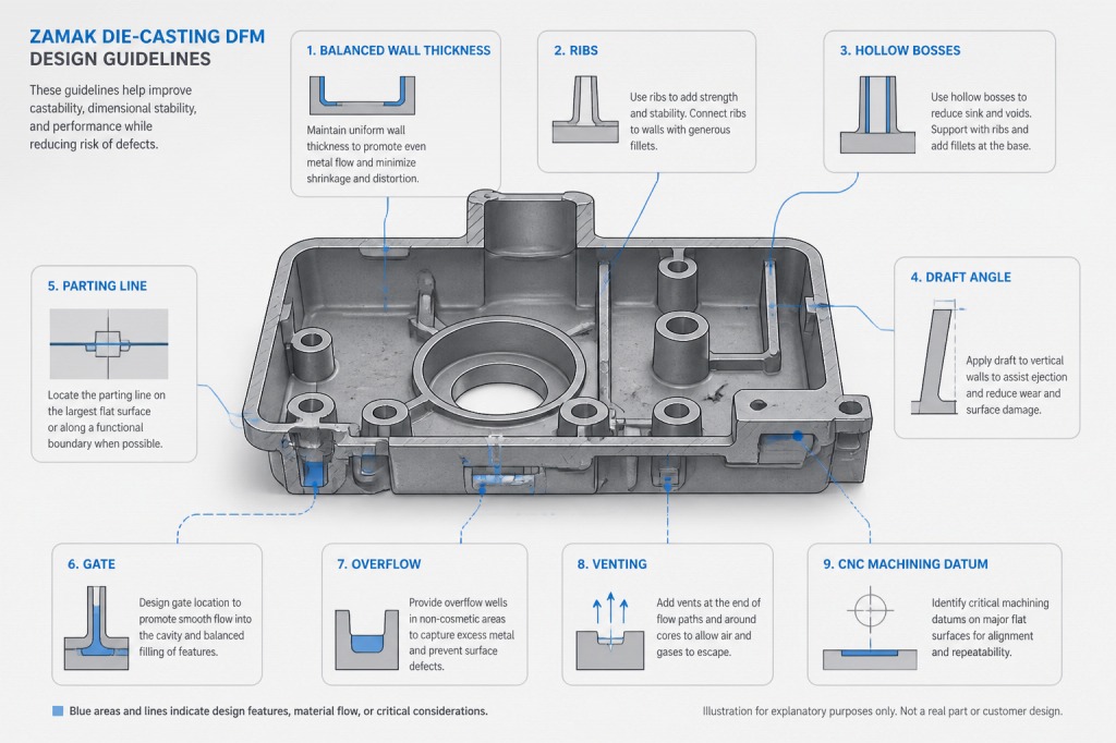
Wall thickness affects filling, solidification, porosity, sink marks, cooling, ejection, and distortion at the same time. For many Zamak parts, a wall in the region of 1.2–2.0 mm is a reasonable starting point for a design conversation. Some geometries can be thinner. A section around 0.8 mm or below needs a closer look at flow length, gate position, venting, die temperature, surface requirements, and the selected grade. It is not a universal capability statement.
A thick section stays liquid longer than a thin section. If the two meet abruptly, the thick area may continue to shrink while surrounding metal has already solidified. We usually look for a smoother transition, a hollowed‑out section, or a support rib instead of adding more metal. A radius helps, but a radius alone does not solve a large enclosed mass.
As an early design reference, rib thickness is often kept around 0.6–0.8 times the adjacent base‑wall thickness. The final value depends on rib height, flow direction, the visible surface behind the rib, cooling, venting, and the required structural load. More ribs do not automatically mean a stronger part; an overbuilt pattern can increase sink marks, porosity, distortion, and visual rejection.
A solid boss is a typical place to find a sink mark or internal void. For a screw column or locating boss, we first look at whether the center can be hollowed out, whether support can be moved into ribs, and whether the boss is connected to the outer wall with a smooth transition. For load‑bearing, sealing, or frequently assembled threads, leave room for CNC tapping or another controlled machining operation.
Sharp internal corners can interrupt the flow front, concentrate stress, and leave a fragile corner in the tool steel. A controlled fillet gives the metal a better path and gives the toolmaker a more practical corner to machine and polish. A radius should still be checked with adjacent wall thickness; an oversized radius can simply move the thick spot rather than remove it.
Tooling consequences should be reviewed with die casting mold design and tooling.
Draft is not just a number added to an outside wall. The required angle changes with die depth, texture, polishing, plating, cavity direction, and ejection. Early design references may start around 1°–1.5° for a standard non‑cosmetic wall and around 1.5°–2° for a polished or plated wall, but the actual model, steel condition, texture, and finish must be checked.
Undercuts can be made in Zamak die casting, but they usually require a slide, lifter, or core pull. During review, we ask whether the feature can move into the main pull direction. If it cannot, we check slide access, venting, shutoff condition, wear, maintenance, and whether the parting line can stay out of a high‑visibility area. A slide that works in a sample is not automatically a good production design.
The product designer does not need to draw the final gate and overflow layout, but the model must leave the toolmaker enough space to build one. We are cautious about placing a high‑visibility feature at the end of fill, where the metal front has lost heat and may carry more oxide or trapped air. The result can be a cold shut, flow line, incomplete feature, or a surface that looks acceptable as‑cast but fails after plating.
Overflow pockets give cold metal and displaced air somewhere to go. Vents and overflows do not replace correct filling design, but removing them from the model leaves fewer ways to manage end‑of‑fill conditions. Deep pockets and enclosed cavities may need an additional venting route, a different filling direction, an overflow location, or a geometry change that makes the area accessible to machining.
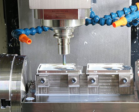
A drawing with tight tolerances on every dimension is not automatically a better drawing. Locating holes, sealing faces, bearing seats, precision threads, and critical assembly datums may need CNC machining. The casting then provides the stock and reference surfaces for that operation.
Is a dimension measured as‑cast, after trimming, after CNC, after plating, or after assembly? Which datum is used? Is the part supported in a fixture or resting freely? A tolerance without those details can produce two different inspection results from the same part. For inspection status and report expectations, review our quality control process.
Electroplating and PVD add material to surfaces. Before tooling, check holes, sliding features, snap fits, threaded areas, and visible assembly gaps so the finish is included in the tolerance budget.
On a perfume cap, smart‑lock panel, or beauty‑device housing, not every surface carries the same visual or functional risk. If the drawing calls every face “zero defect,” the supplier and customer still may not agree on what that means.
Parting lines, ejector marks, gates, and trimming areas should be placed in the hidden or functional zone where the structure permits. For plated and PVD parts, reference samples and viewing conditions need to be agreed before production.
When a customer finds blisters after chrome, gold, or another decorative finish, we do not start by saying the plating line failed. First we check whether the blister sits over subsurface porosity, a pit opened during polishing, a trimming mark, or a region with poor cleaning or activation.
Casting density, surface preparation, polishing, cleaning, activation, sealing or base layers, plating chemistry, baking, and coating adhesion can all contribute. A plating line cannot repair internal casting porosity. If a void opens during polishing or heating, the finish may lift even when plating parameters are within their normal window. Review the related Zamak electroplating process and die‑casting surface finishing options.
The basic DFM rules apply to both grades: balanced walls, sensible ribs, usable draft, controlled bosses, practical venting, and clear machining datums. Zamak 3 is often considered when a balanced combination of castability, dimensional behavior, and finish compatibility is needed. Zamak 5 may be attractive when higher strength or hardness is needed, but the team should review ductility, assembly loads, wear areas, material control, and the required finish rather than assuming the stronger grade is automatically better.
DFM is the engineering review of the part, alloy, die layout, casting process, machining, finishing, and inspection before tooling. It identifies decisions that could create filling, cooling, ejection, dimensional, or surface problems later. It does not replace toolmaking, sampling, or production validation.
There is no single wall thickness for every Zamak part. A region around 1.2–2.0 mm can be a useful starting point, but grade, flow length, geometry, gate and venting, die design, and finish determine the applicable value.
Yes. Undercuts usually require slides, lifters, or core pulls, which affect tooling cost, parting lines, venting, wear, maintenance, and sampling.
The decision depends on thread size, load, assembly frequency, sealing, and volume. Important threads often deserve a machining route or a defined machining contingency.
A blister may involve subsurface porosity, a pit opened during polishing, cleaning or activation, base‑layer problems, baking, coating adhesion, or plating conditions. The casting location and finish preparation should be reviewed together.
No. DFM reduces design and tooling‑related risk; alloy control, machine settings, die condition, finishing, inspection, and production discipline still affect final parts.
Submit the 3D model, 2D drawing, target grade, finish, annual volume, critical dimensions, mating parts, and assembly requirements through the project inquiry form.
Send your 3D CAD model, 2D drawing, target Zamak grade, surface‑finish requirements, critical dimensions, estimated volume, mating parts, and assembly requirements. The engineering team can then review casting, tooling, machining, finishing, and inspection risks before the tooling route is finalized.